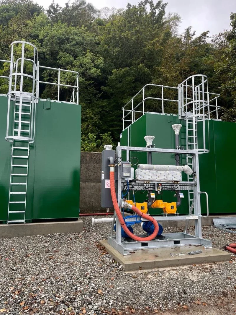
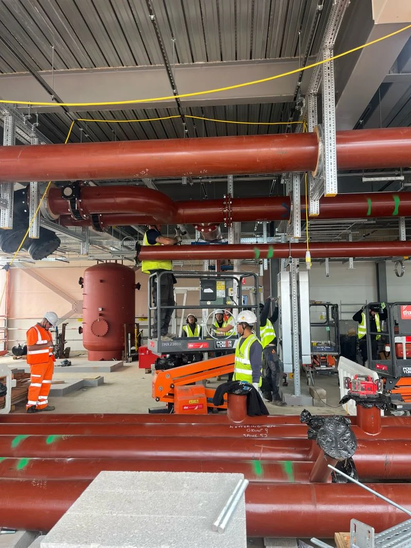
Hydrogen pipework testing must establish that fabricated assemblies meet their approved specification before they enter service. Pressure testing, leak testing and weld inspection serve different purposes. Passing one examination does not automatically demonstrate compliance with every requirement of a hydrogen installation.
For engineering managers, contractors and project teams, the starting point is an agreed inspection and test plan (ITP). This defines the required activities, their sequence, acceptance criteria and the parties authorised to witness or approve them.
This guide focuses on fabricated gaseous hydrogen pipework in industrial installations. Pipeline surveillance and cryogenic liquid hydrogen systems may require different arrangements.
Key considerations for hydrogen pipework inspection
-
Material and weld traceability should be established before testing begins.
-
Visual inspection and dimensional checks identify fabrication issues that pressure testing alone cannot establish.
-
Radiographic, ultrasonic and surface-testing methods may be specified for weld examination.
-
Hydrostatic pressure testing and gas-based leak testing are different activities, with different hazards and acceptance criteria.
-
The competent designer must define the applicable code, test medium, pressures, procedures and acceptance limits. These stringent requirements are project-specific rather than general rules applied to every metal pipe.
Why does hydrogen pipework require a defined testing strategy?
Hydrogen gas can escape through small imperfections in joints and sealing arrangements. Hydrogen molecules are very small, and leaks may present serious hazards because hydrogen has a wide flammability range, low ignition energy and a flame that can be difficult to see in daylight.
Appropriate gas monitoring and exclusion zones may therefore be specified during relevant testing or commissioning activities. Depending on the material and service conditions, hydrogen exposure may also contribute to hydrogen-assisted degradation or an increased fatigue crack growth rate. These issues must be considered during design and material selection, not treated as problems that a final pressure test can always identify.
For hydrogen pipelines or shorter plant systems, the inspection programme should therefore consider the system’s hydrogen concentration, design pressure, temperature, pressure cycling, joint design and expected service life.
Pressure strength testing does not replace leak-tightness testing, and neither necessarily demonstrates long-term resistance to hydrogen embrittlement. Similarly, successful non-destructive testing (NDT) of a weld does not itself establish the suitability of the parent material for hydrogen service.
For a separate discussion of material grades and susceptibility, see the hydrogen pipework materials guide.
Establishing an inspection and test plan (ITP)
An inspection and test plan identifies the stages at which fabrication is checked against approved drawings, welding procedures and the applicable construction code.
Typical stages include material receipt, cutting and preparation, weld fit-up, completion of welding, NDT, pressure testing, final dimensional checks and handover.
The ITP should identify:
- Drawings, material specifications and applicable codes
- The inspection or testing activity and its acceptance criteria
- Personnel responsible for performing and reviewing the activity
- Witness points and mandatory hold points
- Required records, certificates and release authorisations
- Arrangements for non-conformities and repairs
A hold point prevents work from progressing until the required approval has been obtained. For example, a specification may require examination of a joint before it becomes inaccessible within an assembly. A witness point allows an authorised party to observe a defined activity, according to the agreed notification arrangements.
The concept of inspection hold points helps teams identify issues while welds remain exposed and accessible. The precise stages and approval arrangements depend on the project. They should not be invented by the fabricator after manufacturing begins.
Material inspection and traceability
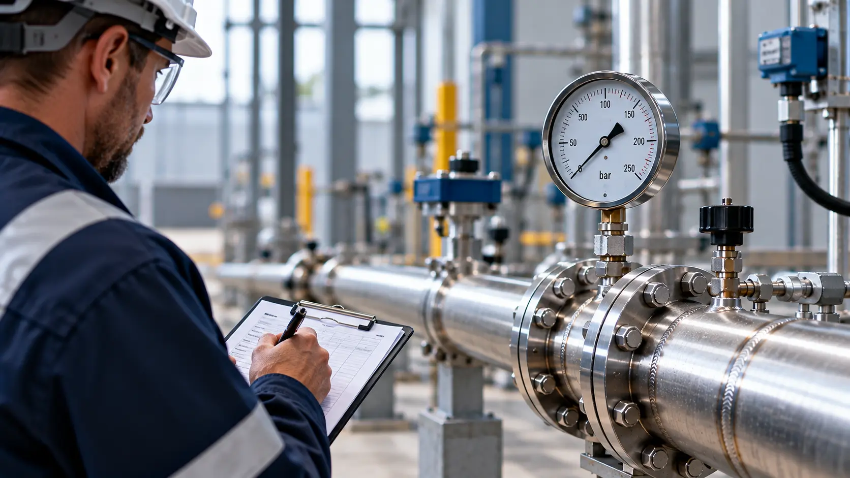
Material verification provides evidence from material certificates and tensile tests, where specified, that the components being fabricated correspond to the approved design.
Relevant records may include mill test certificates, material grade, heat number, product form and applicable mechanical or chemical test results. EN 10204 inspection documents, including type 3.1 certificates, may be specified.
Where sections are cut from longer pipe lengths, the identification and traceability system should allow each pressure-retaining component to be linked back to its source documentation. Fittings, flanges and welding consumables may also require documented identification.
Checks at receipt and before fabrication help identify incorrect grades, mismatched components or substitutions that have not been approved.
For hydrogen service, this is especially important because a broadly similar material designation does not guarantee identical performance under all pressures, temperatures or loading conditions. Material approval remains a design responsibility.
Documentation may include specialist materials analysis, tensile-test data or examination of other alloys when demanded by the service conditions. This evidence is not a substitute for design approval.
Welding procedure and qualification checks
Welding quality is central to industrial pipework integrity. The welding procedure must account for the possibility of cold cracking and the material’s susceptibility, without assuming every steel grade is equally prone to hydrogen damage.
Before welding begins, the project should establish the qualified welding procedure specifications (WPS), supporting procedure qualification records (WPQR/PQR) and required welder qualifications.
Relevant standards may include ASME Section IX, BS EN ISO 15614-1 and BS EN ISO 9606-1 where specified. Their applicability and editions are determined by the project requirements.
Weld records can identify the location of each weld, the procedure used, the welder, inspection results and any repairs. This provides traceability between fabricated joints and the supporting quality documents.
Hydrogen-assisted cold cracking during welding should not be confused with degradation caused by hydrogen exposure during later operation. The appropriate preheat, consumable controls, interpass temperatures, hardness limits or heat treatment must be determined through the applicable welding procedure and specification.
Visual and dimensional inspection
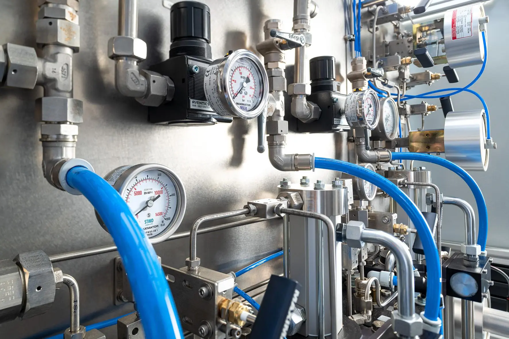
Visual inspection is an important first stage of weld examination. It can identify surface defects or workmanship issues requiring further investigation.
Checks may include weld profile, undercut, visible porosity, surface cracking, arc strikes and the condition of adjacent material. Inspection also considers cleanliness and the preparation of joints scheduled for specialist NDT.
Dimensional checks establish whether fabricated pipe spools match the approved drawings. They may cover:
- Spool lengths and overall dimensions
- Flange orientation and alignment
- Branch connection positions
- Fit-up and joint preparation
- Supports, clearances and installation interfaces
Accurate fabrication helps prevent forced alignment during installation, which can create unintended loads on joints and supports.
The applicable acceptance criteria determine which findings are acceptable and which require remedial action.
Non-destructive testing (NDT) of hydrogen pipework welds
NDT examines material or weld condition without destroying the component. The appropriate methods, examination extent and acceptance criteria depend on the code, material, weld geometry and project specification.
| NDT Method | Common Application |
|---|---|
| Radiographic Testing (RT) | Examination of internal weld discontinuities using radiographic techniques. |
| Ultrasonic Testing (UT) | Detection and assessment of relevant internal discontinuities, subject to technique and access. |
| Liquid Penetrant Testing (PT) | Detection of surface-breaking discontinuities on suitable non-porous materials. |
| Magnetic Particle Testing (MT) | Detection of surface and near-surface discontinuities in suitable ferromagnetic materials. |
No single method detects every type of defect equally well. PT cannot identify internal weld discontinuities, while MT is unsuitable for non-ferromagnetic austenitic stainless steel. Depending on the specification, advanced ultrasonic methods such as phased-array UT may also be considered.
Unlike in line inspection of operational hydrogen pipelines, fabrication-stage NDT takes place before commissioning. Inspection technology and technician competence both influence what can be detected. An inspection strategy may require combinations of methods, qualification of examination procedures and appropriately certified personnel.
Testing may be carried out in a specialist laboratory or conducted on site according to access, safety and procedure requirements. KEE Engineering can coordinate externally provided specialist NDT according to the agreed project requirements.
NDT is not equivalent to hydrogen compatibility testing. A weld may pass the specified examinations while the overall system still requires separate materials-engineering assessment, potentially including fracture toughness testing and mechanical testing under representative exposure conditions.
Hydrostatic pressure testing
Hydrostatic testing uses an approved liquid test medium, commonly water where suitable, to verify pressure integrity under specified conditions.
Compared with gas-based pressure testing, hydrostatic testing generally involves lower stored-energy hazards because liquids are relatively incompressible. It is therefore often preferred where the material, process and cleanliness requirements permit its use.
An approved hydrostatic procedure should establish the test facility or site location, design working pressure and the test boundaries, medium, temperature, pressure, hold conditions, calibrated instrumentation, examination requirements and safe working controls.
Practical considerations include:
- Identifying and isolating components unsuitable for the proposed test
- Removing trapped air where required
- Controlling filling and pressurisation
- Managing test water quality and material compatibility
- Recording results and any observed leakage
- Controlled depressurisation, draining and subsequent drying
There is no single test pressure or hold duration that should be applied to every hydrogen pipework project. These parameters follow the governing specification and approved procedure.
Test results must be recorded in a form that permits review, including the calibration status of instruments and the environmental conditions encountered. A hydrostatic test demonstrates compliance with its defined acceptance criteria; it does not automatically establish the final system’s gas leak-tightness or future hydrogen-service performance.
When is pneumatic pressure testing appropriate?
Pneumatic pressure testing uses a gas rather than a liquid. It may be considered where introducing water is unsuitable or where the relevant specification permits a gas-based test.
However, compressed gas stores significant energy, so severe consequences can follow failure of the test boundary. An unexpected rupture can create a substantially different hazard from an equivalent hydrostatic test.
A pneumatic procedure therefore requires specific engineering justification, risk assessment and controls. These may address exclusion zones, controlled pressure stages, instrumentation, remotely monitored conditions and the suitability of the chosen test gas.
Air or oxygen-containing media must not be assumed suitable for a particular hydrogen installation. Test-medium selection, isolation, purging and subsequent commissioning arrangements need to follow the approved safety procedure.
KEE Engineering’s established pipework capability includes hydrostatic testing where suitable and coordination of specialist testing. Pneumatic testing arrangements must be reviewed against the individual project’s requirements and delivery responsibilities.
Test media, cleanliness and drying
A successful pressure test can still leave contamination that is unacceptable for subsequent operation.
For example, residual water may cause corrosion or interfere with downstream equipment. Water quality can also matter for corrosion-sensitive materials, including certain stainless steel applications.
Before introducing hydrogen, the project may require controlled draining, drying, cleaning, flushing or inert-gas purging. Inert-gas purging may be needed to prevent formation of flammable hydrogen-air mixtures during commissioning; the method and verification criteria must be specified by the responsible engineer. The specified methods and acceptance criteria depend on the system and its intended use.
Fabrication debris, weld spatter, oil, temporary test fittings and other foreign materials should be addressed through the agreed cleanliness requirements.
Drying, cleanliness and purge completion should be documented where the inspection and commissioning plan requires it. A pressure-test certificate alone does not establish that a system is ready for hydrogen introduction.
Leak-tightness testing and helium methods
Leak testing aims to identify unacceptable leakage at joints, welds, valves, fittings or other pressure boundaries. This is separate from demonstrating pressure strength.
Possible methods include examination during hydrostatic testing, suitable bubble-testing methods, controlled pressure-decay techniques or more sensitive tracer-gas methods where specified. Bubble leakage tests typically use an appropriate leak-detection solution applied to accessible joints under an approved gas-test procedure. Ultrasonic leak-detection instruments may help locate escaping gas from exposed connections, subject to method suitability and background conditions.
Helium leak testing may be selected when a project requires sensitive detection of leakage using specialised equipment. The suitability of a helium method depends on the test arrangement, required sensitivity and agreed acceptance criteria. The specialist provider should discuss detection capability, test boundaries and relevant background gas concentrations with the project team before the test is developed.
Specialist helium and tracer-gas testing must not be confused with ordinary workshop visual inspection. KEE Engineering can coordinate externally arranged specialist testing where required; helium leak testing is not presented as an established in-house KEE capability.
The required permissible leak rate, test pressure, test duration and pass/fail criteria must come from the designer and applicable specification. A component described as ‘hydrogen-rated’ does not remove the need to verify its suitability for the installed system.
Final inspection, documentation and handover
The handover process should bring together the records required to demonstrate that fabrication and testing have been completed in accordance with the approved scope.
Depending on the project, the handover pack may contain:
- Material certificates and traceability schedules
- Approved WPS/WPQR and welder qualification records
- Weld maps and non-conformance or repair records
- Visual, dimensional and specialist NDT reports
- Pressure-test and leak-test certificates
- Inspection and test plan sign-offs
- Final drawings and agreed installation documentation
Independent inspection or verification may also be required by the specification, contractual arrangements or applicable regulatory framework. Any failed result should trigger documented investigation and corrective action. After repair, the necessary examination and retesting must be carried out under the approved procedure, rather than assuming the original test remains valid.
Commissioning and the introduction of hydrogen require their own controls and authorisations. Where hydrogen gas is introduced, appropriate fire and explosion risk controls must be established by the responsible parties. Fabrication completion should not be treated as automatic permission to put the system into service.
Relevant standards for UK hydrogen pipework
ASME B31.12 addresses hydrogen piping and pipelines within its scope. ASME B31.3 addresses process piping. Other standards, such as relevant BS EN pipework standards, may apply according to the project and jurisdiction.
Welding qualifications, NDT procedures and pressure testing can also be governed by separate referenced standards.
The governing design authority must establish the appropriate documents and acceptance criteria. New industry research may inform future code development, but does not override the edition adopted for the project. A statement that a system is tested ‘to ASME standards’ is insufficient without identifying the applicable provisions and actual project records.
How KEE Engineering supports specification-led pipework testing
KEE Engineering provides workshop fabrication, coded welding and on-site installation services for industrial pipework projects throughout the UK.
Its established quality-related capabilities include visual and dimensional checks, suitable hydrostatic testing and coordination of specialist NDT. These activities can form part of the project-specific inspection and test plan for proposed hydrogen pipework where the required procedures, qualifications and resources are confirmed.
The company does not claim completed hydrogen-specific projects or universal approval for hydrogen service solely on the basis of its conventional industrial pipework experience.
For more information, visit KEE Engineering’s hydrogen pipework fabrication services or contact the team with your drawings, material specification, testing requirements and proposed programme.
Frequently asked questions
Is hydrostatic testing sufficient for hydrogen pipework?
Not necessarily. Hydrostatic testing checks pressure integrity under an approved procedure, but the project may also require gas leak-tightness testing, weld NDT and material verification. The design authority specifies the combination of examinations required.
Can hydrogen pipework be pressure tested with nitrogen?
Nitrogen may be appropriate for certain gas-based testing or purging activities where the approved procedure permits it. Its use does not remove the stored-energy hazards of pneumatic testing, and it should not be selected without a project-specific risk assessment.
What NDT methods are used for hydrogen pipework welds?
Depending on the specified material, joint and acceptance criteria, radiographic, ultrasonic, liquid penetrant or magnetic particle testing may be appropriate. Qualified specialists should undertake the examinations required by the project.
Is helium leak testing mandatory for hydrogen systems?
No universal requirement applies to every installation. Helium testing can be useful where the designer specifies high-sensitivity leak detection, but the selected method and acceptance criteria depend on the particular system.
Who approves hydrogen pipework testing requirements?
The appointed competent designer or responsible engineering authority establishes the applicable standards, test conditions and acceptance criteria. The agreed inspection and test plan identifies which parties perform, witness and approve each activity.